Product Description
Product Description
1. The allowable compensation quantity listed in the table refers to the relative offset of 2 axes formed by the comprehensive factors such as vibration, shock, deformation and temperature change caused by manufacturing error, installation error and working load change under working condition.
2. The maximum allowable angular deviation of the coupling shall not exceed ±5°.
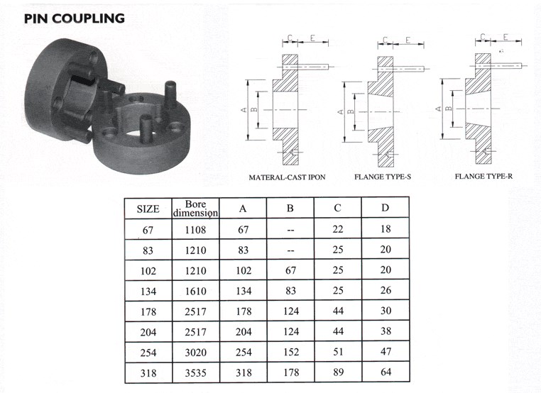
The maximum opening value is a circular hole or a tapered hole with a keyway.
Main applications:
DWZ disc eddy current brake is mainly used as load in loading dynamometer equipment. it is experimental apparatus which can measure the dynamic mechanical properties, especially in dynamic loading test whose power value is small or tiny, also can be treated as suction power devices of other dynamic devices.
DW series disc eddy current dynamometer is, is that add device for measuring torque and rotational speed on DWZ series disc eddy current brake, it is experimental apparatus which can measure the dynamic mechnical properties, especial in dynamic loading test whose power value is small or tiny.
CW eddy current brake as a load is mainly used to measure the mechanical characteristics of inspection equipment, it and other control instrument (including loading apparatus, torque speed sensor and torque power acquisition instrument etc.) can be composed of eddy current dynamometer can be used for performance testing of the internal combustion engine, motor, gas turbine, automobile and its dynamic mechanical components, compared with other power measuring device, the CW series power measuring device has the advantages of reliability, high stability and practicability.
| Eddy current brake/dynamometer | Rated Power | Rated torque | Rated speed | Maximum rotational speed | Turning inertia | Maximum excitation voltage | Maximum excitation Current | Cooling water pressure | Flow of the cooling water |
| DWZ/DW-0.75 | 0.75 | 5 | 2000-2600 | 16000 | 0.002 | 80 | 3 | 0.1~0.3 | 1 |
| DWZ/DW-3 | 3 | 10 | 2000-2600 | 14000 | 0.003 | 80 | 3 | 0.1~0.3 | 2 |
| DWZ/DW-6 | 6 | 25 | 2000-2600 | 14000 | 0.003 | 80 | 3 | 0.1~0.3 | 3 |
| DWZ/DW-10 | 10 | 50 | 2000-2600 | 13000 | 0.01 | 80 | 3 | 0.1~0.3 | 4.5 |
| DWZ/DW-16 | 16 | 70 | 2000-2600 | 13000 | 0.02 | 80 | 3.5 | 0.1~0.3 | 6.5 |
| DWZ/DW-25 | 25 | 120 | 2000-2600 | 11000 | 0.05 | 80 | 3.5 | 0.1~0.3 | 15 |
| DWZ/DW-40 | 40 | 160 | 2000-2600 | 10000 | 0.1 | 90 | 4 | 0.1~0.3 | 25 |
| DWZ/DW-63 | 63 | 250 | 2000-2600 | 9000 | 0.18 | 90 | 4 | 0.1~0.3 | 45 |
| DWZ/DW-100 | 100 | 400 | 2000-2600 | 8500 | 0.32 | 120 | 4 | 0.1~0.3 | 60 |
| DWZ/DW-160 | 160 | 600 | 2000-2600 | 8000 | 0.52 | 120 | 5 | 0.1~0.3 | 100 |
| DWZ/DW-250 | 250 | 1100 | 2000-2600 | 7000 | 1.8 | 150 | 5 | 0.2~0.4 | 180 |
| DWZ/DW-300 | 300 | 1600 | 2000-2600 | 6000 | 2.7 | 150 | 5 | 0.2~0.4 | 210 |
| DWZ/DW-400 | 400 | 2200 | 2000-2600 | 5000 | 3.6 | 180 | 10 | 0.2~0.4 | 300 |
| DWZ/DW-630 | 630 | 3600 | 2000-2600 | 5000 | 5.3 | 180 | 10 | 0.2~0.4 | 450 |
/* January 22, 2571 19:08:37 */!function(){function s(e,r){var a,o={};try{e&&e.split(“,”).forEach(function(e,t){e&&(a=e.match(/(.*?):(.*)$/))&&1
| Standard Or Nonstandard: | Nonstandard |
|---|---|
| Shaft Hole: | 19-32 |
| Torque: | 70-80N.M |
| Bore Diameter: | 19mm |
| Speed: | 10000r/M |
| Structure: | Flexible |
| Customization: |
Available
| Customized Request |
|---|
Can Pin Couplings Accommodate High Torque and High-Speed Applications?
Pin couplings are versatile and robust, making them suitable for a wide range of applications, including those involving high torque and high-speed requirements. However, the specific design and construction of the pin coupling will determine its capacity to handle such demanding conditions.
The ability of a pin coupling to accommodate high torque depends on factors such as the material used, the size and number of pins, and the overall design. High-quality pin couplings are often made from strong and durable materials like alloy steel, which allows them to withstand significant torque loads without failure or deformation.
Similarly, the capability of a pin coupling to handle high speeds depends on factors such as the balance of the coupling and the precise manufacturing of the pins and hubs. Properly balanced pin couplings can operate at higher speeds without generating excessive vibration or causing premature wear.
When selecting a pin coupling for high torque and high-speed applications, it is essential to consider the following:
- Design and Construction: Opt for pin couplings with a robust and well-engineered design to handle the expected torque and speed requirements.
- Material: Choose pin couplings made from high-quality materials known for their strength and fatigue resistance.
- Size: Select an appropriate size of pin coupling that can accommodate the torque and speed expected in the application.
- Manufacturer’s Ratings: Refer to the manufacturer’s specifications and torque-speed curves to ensure the coupling meets the desired performance criteria.
By carefully considering these factors and choosing a pin coupling designed for high torque and high-speed applications, you can ensure reliable and efficient power transmission in demanding industrial settings.
How Does a Pin Coupling Handle Angular, Parallel, and Axial Misalignment?
A pin coupling is designed to handle different types of misalignment, including angular, parallel, and axial misalignment. The unique construction of pin couplings allows them to accommodate these misalignments without compromising the efficiency and performance of the connected equipment.
1. Angular Misalignment: Angular misalignment occurs when the axes of the driving and driven shafts are not parallel but intersect at an angle. Pin couplings can tolerate angular misalignment because of their flexible and floating pin design. The two coupling halves are connected by a series of pins, which can pivot and move within the pin holes. This flexibility allows the coupling to bend slightly, adjusting to the angle of misalignment between the shafts.
2. Parallel Misalignment: Parallel misalignment happens when the axes of the driving and driven shafts are parallel, but they are laterally displaced from each other. Pin couplings can handle parallel misalignment to some extent due to the floating nature of the pins. The pins can move laterally within the pin holes, allowing the coupling to adapt to the offset between the shafts.
3. Axial Misalignment: Axial misalignment occurs when there is a linear displacement along the axis of one shaft concerning the other. While pin couplings primarily focus on handling angular and parallel misalignment, they may offer limited axial misalignment capabilities. The floating pins provide a small degree of axial movement, but excessive axial misalignment is best avoided to prevent additional stresses on the coupling.
It is important to note that while pin couplings can accommodate some degree of misalignment, excessive misalignment should be avoided to prevent premature wear and potential failure of the coupling and connected equipment. Regular inspection and maintenance can help identify and address any misalignment issues, ensuring the optimal performance and longevity of the pin coupling in power transmission applications.
Can Pin Couplings Handle Misalignment Between Shafts?
Yes, pin couplings are designed to accommodate a certain degree of misalignment between shafts in rotating machinery. They are considered flexible couplings, which means they can provide some degree of angular, parallel, and axial misalignment capability.
Pin couplings typically consist of two hubs, each connected to a shaft, and a central sleeve with pins that transmit torque between the hubs. The pins allow for a limited range of movement, which helps to compensate for slight misalignments between the shafts.
The angular misalignment capacity of a pin coupling is achieved through the bending of the pins. When the shafts are misaligned at an angle, the pins on one side of the coupling experience bending while those on the opposite side are in tension. The pins are designed to withstand these bending and tension forces within their elastic limits, ensuring proper functioning and longevity of the coupling.
Similarly, the pins can accommodate parallel misalignment by sliding within the pin holes of the coupling’s central sleeve. This sliding action allows the hubs to move slightly relative to each other, compensating for any offset between the shafts.
However, it is essential to note that pin couplings have limitations in terms of the amount of misalignment they can handle. Excessive misalignment beyond their specified limits can lead to increased wear on the pins and other coupling components, reducing the coupling’s effectiveness and potentially causing premature failure.
While pin couplings are suitable for applications with moderate misalignment requirements, they may not be the best choice for applications with significant misalignment or where precise alignment is critical. In such cases, more flexible couplings like gear or elastomeric couplings may be more appropriate.
Overall, when considering the use of pin couplings, it is essential to carefully evaluate the specific misalignment requirements of the application and select a coupling that can adequately accommodate those misalignments while ensuring reliable and efficient power transmission.


editor by CX 2024-05-06
by
Tags:
Leave a Reply